"Robot Inventors" Activity Guide
"Robot Inventors" Activity Guide
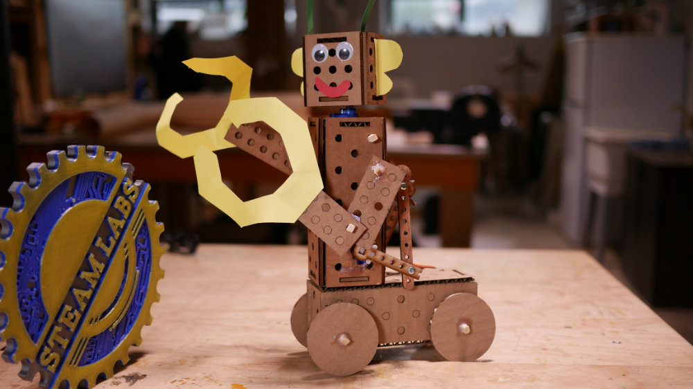
A robot made with the cardboard construction parts.
Activity Description
In this activity, participants will build their very own robot companion! They supply the imagination, and we supply the robotic parts, building materials and mentoring to bring their ideas to life. At the end of the sessions, each participant gets to bring their new robot home!
Each participant will receive an assortment of laser cut robot construction parts, servo motors, control knobs, LEDs and a battery pack. These can be put together to make a robot that can swivel and move on command.
This event is designed to work best as a 3 hour activity, and is intended for makers of 8 or older. It requires a laser cutter to prepare the cardboard and plywood parts.
Equipment & Materials
> Tools
- Laser cutter
- Glue guns
- Scissors
- Mitre shears
> Craft Materials
- Single and double-ply cardboard
- ⅛” and ¼” plywood
- Rectangular chopsticks
- Construction paper
- Glue-sticks
- String
- Googly eyes
> Electronics
- SG90 servos
- Servo controllers
- 4xAA battery pack
- LEDs
- Button cells
- DC motors
> Adobe Illustrator Files
12" x 24" laser bed:
Setup
- Pre-cut cardboard and plywood parts. The numbers below of parts per participant should be more than sufficient and leave parts for subsequent activities:
- Cardboard: two chassis boxes, one head box, six end pieces, four limbs, one jaw, four wheels
- Plywood (¼”): two sets of gears, two elastic hooks, four torque bars
- Plywood (⅛”): eight connector pegs
- Collect other parts, such as paper, small sheets of cardboard, elastics, string, straws, chopsticks, etc.
- Gather relevant tools: glue guns, scissors, and mitre shears to cut chopsticks (for the purposes of safety, the each set of shears should probably be assigned to an instructor who keeps them on their person).
- Briefly review this guide with instructors, in particular reviewing the appendices outlining different types of mechanisms and joints.
- Have several examples of mechanisms available to demonstrate the possibilities of the activity and aid the participants, but not of projects so complete and polished that they might unduly influence participants’ creativity. E.g. present a functional DC motor belt drive that spins an axle, but without an attachment (so they can imagine the mechanism serving to move wheels, a windmill, or battle-bot flail arms).
Running the Activity
> Introduction
- Welcome party into workspace with general questions and statements:
- Does anyone know why we’re here today and what we’re doing?
- Today we’ll be inventing cool robots!
> Safety Expectations
- Introduce expectations at the beginning of the event. Discuss and write them on a piece of chart paper. Expectations include:
- Respect everyone and everything! This includes kids, mentors, tools, and space.
- No physical or verbal violence!
- No running.
- Pause your conversations when a teacher or mentor are addressing the group.
- Always have a mentor turn on and assist with the use of any of the more complicated in the space.
- Stay in the class area unless accompanied by a mentor.
- Highlight places that are out of bounds.
- Have fun!
> Demonstrate Robot Parts & Electronics
- Hand out all the supplies to each kid.
- Go over each item and explain its function.
- Explain function of button cells, LEDs, batteries, servos, servo controllers, and DC motors. Demonstrate each part in turn.
- Explain the connections between parts, such as the colour coding of wires and the effects they have on different parts.
> Ideation & Planning
- Having provided the parts and demonstrated their functionality, encourage participants to take time to specifically imagine what they want to build with writing and illustrations on a sheet of blank paper.
- Encourage them to roughly outline the steps they will need to take to create their design on the same sheet.
- This stage serves to help participants plan and to highlight unrealistic goals, but also provides a valuable means for mentors to refocus participants and to understand what participants want to accomplish.
> Assembly
- Allow participants to begin their constructions when their plan is sufficient.
- Have mentors circulate among participants to provide help with difficult issues and to operate larger tools.
- Encourage participants to view problems they encounter positively, as challenges to be overcome, learning opportunities, anecdotes for their presentations, or chances to rethink their designs.
- For participants who finish their designs early, encourage decoration and elaboration.
- Wind down assembly activity, providing significant, regular notices of when the activity will end (e.g. 30 mins, 15 mins, 5 mins, etc.).
> Showcase Creations
- Allow participants to showcase their creations to the group.
- Allow small, non-disruptive tweaks and last minute adjustments during this time.
> Post-Activity (for educators)
- Clean the work area.
- Reclaim discarded, usable parts for subsequent classes.
- Debrief mentors, addressing issues and noting successful or ineffective strategies.
Appendix #1: Examples of Mechanisms & Joints
Chassis & Head Boxes
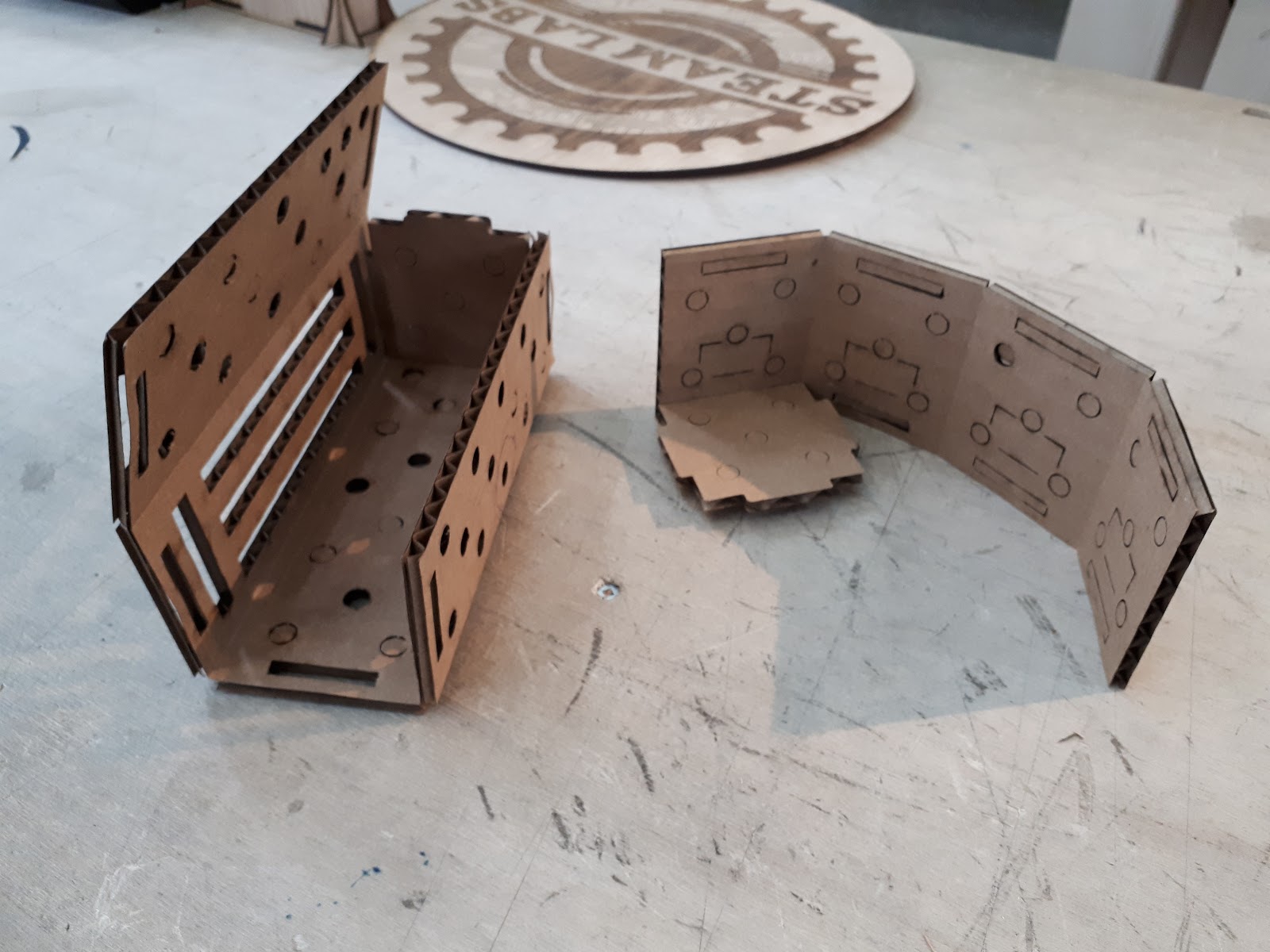
Basic building blocks of this activity. Covered in holes to allow axles and other parts to run through them.
Printed flat. Assembled with end pieces, which slot into the boxes in two spots on each face to create a rectangular prism
Axles
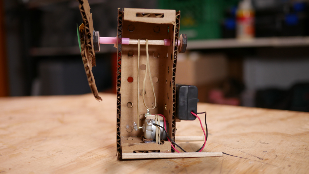
Created with chopsticks. If friction is too great, these can be run through medium size straws (which should fit snugly in the holes in the chassis).
These can be attached to wheels or to other body parts (like arms or heads) and controlled with a lever.
Flat Joints

Made with two connector pegs, these form a swivel joint between two sheets of cardboard.
Control Levers

Slot onto chopsticks in axles, to allow the axle to be controlled like a puppet.
These have holes cut in them, which can allow you to form joints with nuts and bolts.
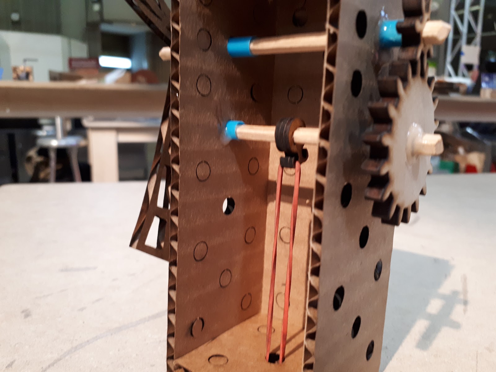
Elastic Band Drive

Propels robots or vehicles with tensed elastic wrapped around hook attached to an axle. Must be hand-wound.
The same system can attach to a wired DC motor rather than a fixed point, to create a belt drive that provides continuous rotation to an axle.
DC Motor Elastic Drive
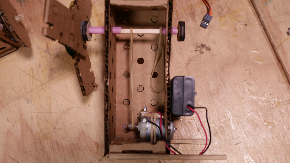
The same system can attach to a wired DC motor rather than a fixed point, to create a belt drive that provides continuous rotation to an axle
Gears
Sized to mesh when fit into two orthogonal holes on the chassis box. Can be used to transfer motion or amplify it (e.g. to make an elastic band drive create more rotations).
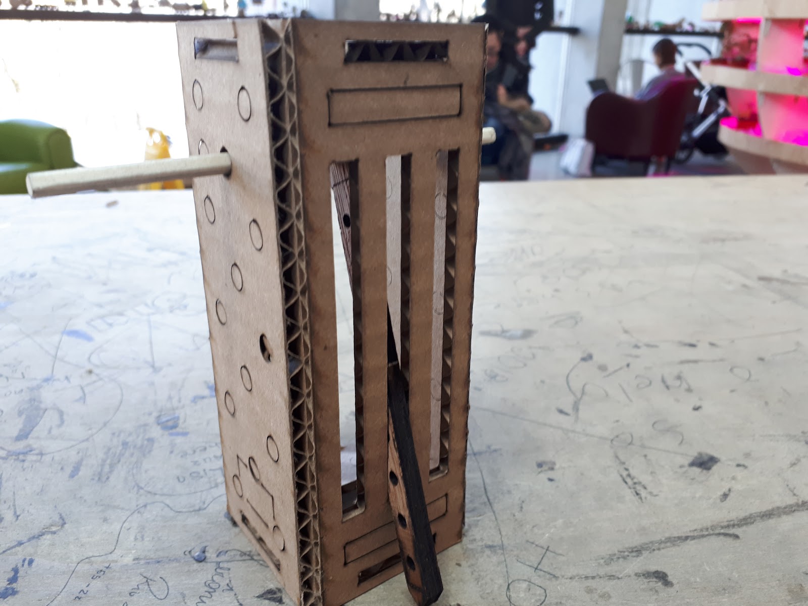
“Jaws”

Cardboard part that folds into three sections and fits over the end of a chassis. Good for creating a moving jaw piece.
Connecting Rods

Allow objects to be pushed and pulled at a distance (like an object moving forward and backwards or a swinging hinge/limb).
Using a bendy drinking straw as a rod allows the rod to bend with a hinge.
Flanged End Pieces

Replace regular end pieces. Help stabilize connecting rods, keeping their motion controlled.
Can be made from cardboard or wood (for greater durability).
Servos

Can automate the movement of levers and rods.
The chassis and head boxes have servo shaped cut out lines on them, to make them easier to install. Some end pieces also have servo-shaped holes cut into them in the place of a centre hole.
Appendix #2: Attaching Servos
If you intend to add a servo to creation, always start by creating the mechanism first and placing the servo afterwards.
It is helpful to place the axle at a very high position inside the box. This will make the effect of the servo much more exaggerated.
Servos can be easily mounted in the rectangular outlines on the sides of the boxes.

Linking arms can be attached with M8 bolts passed through the holes cut along their length. Excess wooden arm length can be cut off with the mitre shears.

Leaving nuts and bolts loosely attached (and applying hot-glue to the ends to prevent it from falling apart entirely) can be useful to allow the control linkages to flex side-to-side.

The last control bar can be hot-glued to the horns of the servo to connect the mechanism and the actuator.
